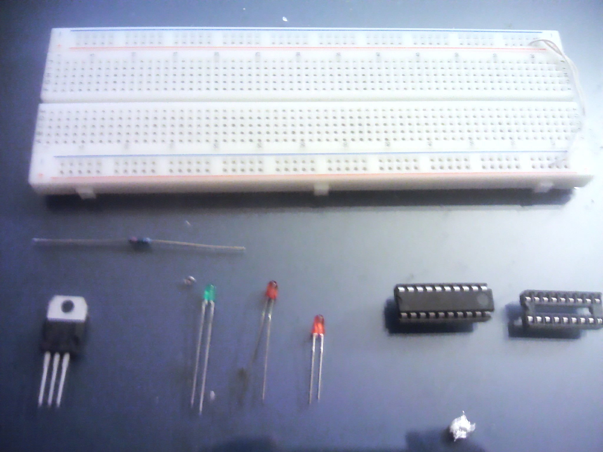
Well, well. Now that you know how to write, build, and flash your code, we can start making our first circuit! Traditionally, in the coding world one prints on the screen the classic “Hello World!” message. In electronics, due to the lack of the “screen”, we just blink LED’s! “But what do I need to get to do that?”, you ask? Here’s a short list for this small circuit, in case you are starting from the ground up:
1 – AC/DC Adapter or some kind of DC PSU (not pictured)
2 – Breadboard
3 – L7805CV (bottom left) – Optional, but it’s a common usage component, and it won’t hurt. It’s used to make sure that your circuit only gets 5V, even if your adapter freaks out and puts 12V on your breadboard. Must have if you are using cheap adapters
4 – 150 ohm resistor for the power led
5 – 3 mm LED’s (I used 2 red and 1 green)
6 – The trusty ATTiny 2313A
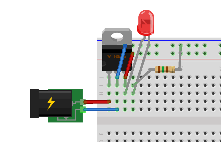
7 – 20 pin socket (bottom right) – Good if need to move your IC around, and want it to have all it’s legs in the end of the day.First, we’ll take care of that voltage regulator and power led. Make your circuit like this:
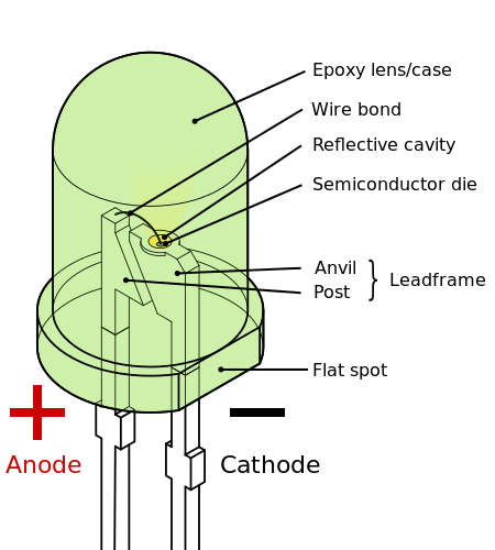
Now when you plug your adapter with 5v in the DC jack, the led should light up. Watch out for the polarity of the led:
- The side with less internal area is the positive side.
Time for the real part of our circuit. First let’s go see the 2313 datasheet for important details:
Pin 20 VCC
Pin 10 GND
Voltage on any Pin except RESET
with respect to Ground …………………………..-0.5V to VCC+0.5VDC Current per I/O Pin ……………………………………….. 40.0 mA
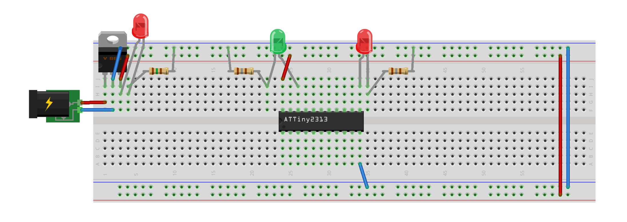
So, we must connect pin 20 to VCC and pin 10 to GND. It is also important to notice the maximum voltage and current rating on our I/O pins. This tells us that we must limit our led’s with resistors. We can go here to get a value quickly. Put in 5.5 (our voltage regulator VCC + 0.5), 2.2 and 20, as the values, and you’ll get a resistor value of 180 ohm. Assembly time!
In the next post we’ll code the blink program for both the led’s. See you soon!


Pingback: My First AVR Circuit II: Source Code | Electro Sparrow