
Hey all! Again, sorry for the long delay in posting.
I’ve recently projected and built a bench top PSU for my electronic projects. It’s based on the LM317 voltage regulator, for which TI granted me samples. The hole idea behind this is to get a PSU that can have both fixed and adjustable voltage output. Instead of having it connected to mains, we’ll use a laptop power adapter to power it (mine is an HP brick, running at 19V). Note: Be aware that you should give it at least more than 3V in than you want on the output. That is, if you want 5V output, the input should be at least 8V.
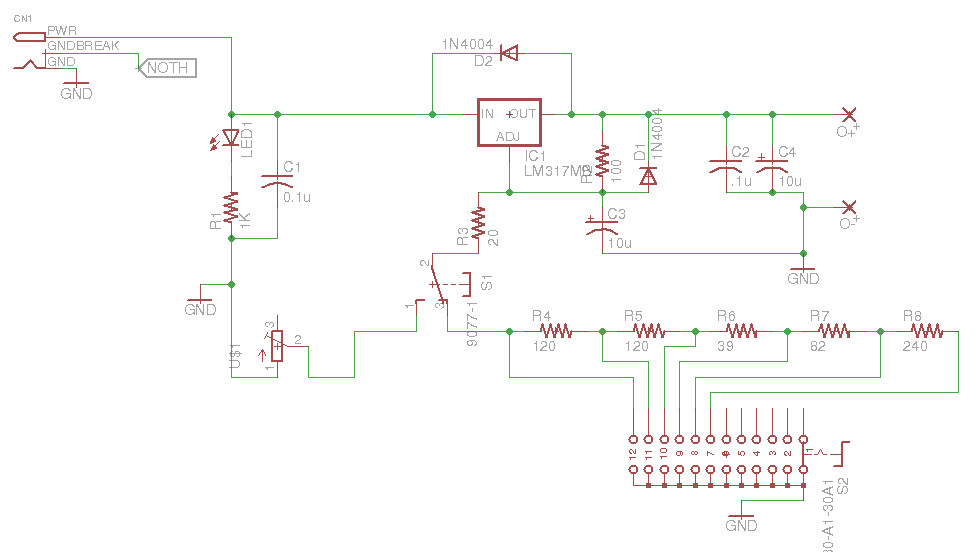
Power Supply Schematic
Let’s get down to it. The LM317 is a voltage regulator that can handle 3-40V input, and capable of supplying 1.25-37V @ 1.5A. This is great for simple electronic projects, and since it has thermal overload protection, you probably won’t end up burning it. To make it work, we only need to choose 2 resistors, using “the maths”, or widely available calculators. Since we want it to be variable, we just use a switch or a potentiometer, depending on the mode.
The parts required for this project are:
1 – LM317
2 – Resistors: 1KΩ (1/2W), 20Ω, 39Ω, 82Ω, 100Ω, 2*120Ω, 240Ω
3 – Potentiometer: 680Ω (or 1KΩ). You can also use combinations. I use a 1KΩ+500KΩ in series.
4 – Capacitors: 2*0.1µF, 2*10µF (25V)
5 – Diodes: 2*1N4007 (our 1N4001, or something like that. The only difference is the voltage)
6 – Switches: 1 regultar 2 position switch, and a 6 position 1 pole rotary switch. These are more expensive. You can use 6*2 position switches instead, but it’s worse. See this to get an idea.
7 – A simple LED
Once you have all this, you can just assemble it on a breadboard according to the schematic above. The main pointers for this circuit are:
- The left upper part of the circuit it the DC jack and the power LED. The resistor here has to be a 1/2W, since we can have 19V and a lot of amps here, depending on the adapter you use. Mine is a 19V 4.74A (90W).
- The LM317 circuitry is explained in the datasheet, page 7. The resistors circuit define the final voltage, the diodes provide short circuit protection, and the capacitors improve ripple rejection.
- The capactiors in the right end are for decoupling and ripple rejection (prevent noise).
- If you want both the adjustable and fixed output, just use the circuit as it is. The left part of the resistor cuircuit is the adjustable mode, and the right one is the fixed. I used 10% precision resistors, but the final result was acceptable, as can be seen below.
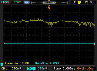
Final result with the laptop adapter. Yellow is the adapter output, Blue is the PSU output.
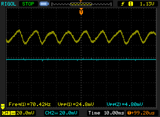
Final result using a cheap 12V adapter. Notice the 24.8mV sinal, versus the 4.8mV of the PSU.
After you test your new awesome PSU on a breadboard, it’s time to make it even more awesome. Get your hands on some protoboard and wire it, or even make your own PCB. You can make something like the one I designed. The idea is to put all the stuff inside a metal case (including the laptop brick), ground the case, and put the potentiometer and the switch on the lateral. Here it is:
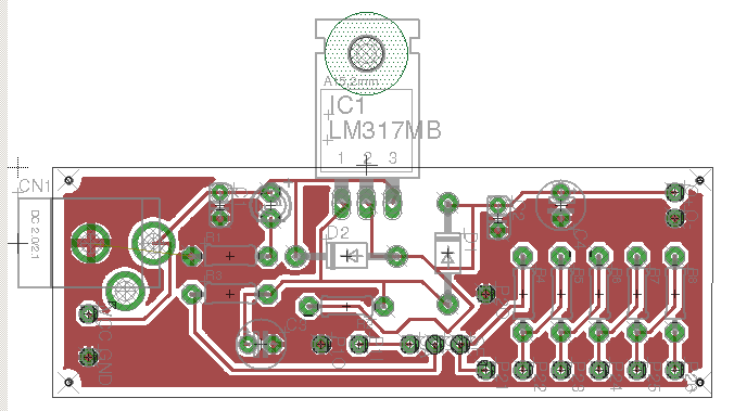
PCB prototype design.
Of course you can add loads of stuff on top of this PSU. How about a LCD voltage meter? We’ll do that on the next post! See you then!