Hello!
For our next project, we’ll be using an ATMega328p and two 7 segment displays to implement a decimal counter. This can be useful if we want to implement a project that gives visual feedback to the user, like a thermometer (our next project).
To implement this, we’re going to rely on the POV phenomenon (Persistence Of Vision) to decrease the number of pins used by the displays to 9: 7 to the “bus”, that tells both displays what segments to lit, and 1 to each display common, to select which one displays each number.
Hardware list:
1 – AC/DC Adapter or some kind of DC PSU (not pictured)
2 – Breadboard
3 – L7805CV (bottom left) – Optional
4 – 150 ohm resistor for the power led – Optional
5 – The trusty ATMega328p – You can use an ATTiny2313A with few source changes.
6 – 28 pin socket (bottom right)
7 – 7*100 ohm resistor for each display segment – Optional, but recommended
8 – 2*Common Cathode Hex display – Again, you can use common anode with just a few source changes.
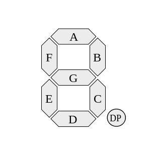
Now, to the wiring! First, you should be familiar with the displays you’re using. It helps a lot if they are the same model. You should download it’s datasheet, and see the pinout. Usually, you have one pin for each segment in the picture bellow, and two common.

Individual segment graphic – From Wikipedia
After you find out which are which, you can start connecting to the ATMega as follows:
A – PD7 B – PD6 C – PD5 D – PD4 E – PD3 F – PD2 G – PD1 DP – Currently not used. You can ground it for nowWhen in doubt, remember to check the display/ATMega datasheet.You should connect both displays pin to the same IC pin. That is, both A pins are connected to PD7. Which means that they both receive the same “bus” information at the same time.
Now, I should probably give you an head’s up: most people would recommend you to use those resistors between your display and your IC. I personally don’t use them, since the currents I use are pretty low, especially with both displays working. Just in case, the warning is given. Do as you see fit.
The only thing left is to connect the commons. You should connect the left display commons to PB2 IC pin, and the right one to PB1 IC pin.
Done! The only thing left is to connect the supply to the IC itself. You can do this by connecting both ground, and the VCC, reset and AVCC with 5V from the circuit we made last time.
Next time I’m gonna provide the source and hex files ready to burn, and the final look on the project. See you then!

Use the resistors. I bought a couple 7 segment displays from Radio Shack, hooked them up to my Atmega328p-pu, and poof went all the pins hooked to the displays. After testing the amps, the LEDs drew nearly 700mA which far exceeded the 50mA max rating of the IC. Throwing a single 150-200ohm resistor (I think, been a while) on the common cathode dropped the consumption down to around 20mA.
Yes, and that’s exactly what I do for production. For development projects, I’ve never done it, and never had any problem. Then again, it is better to be safe, hence the warnings on the post. But thank you for your answer, shedding light on the subject! 😉